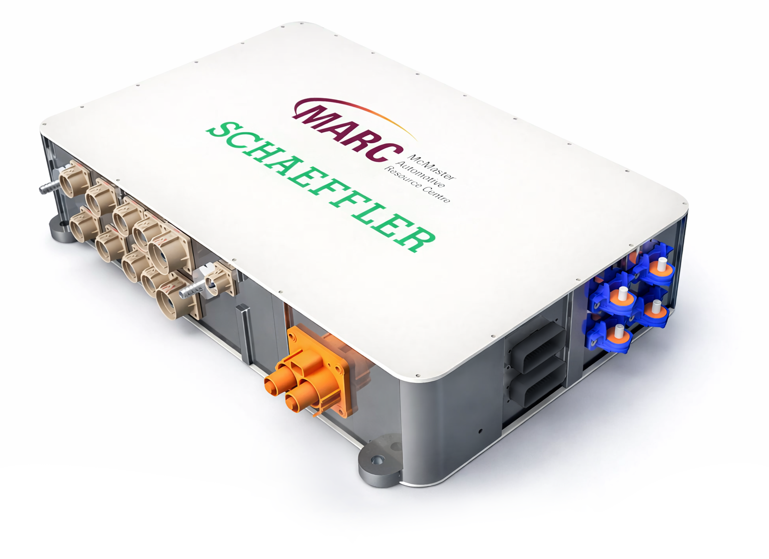
4-IN-1 High Power Electronics Converter
Cooling system design, developed for Schaeffler Group
About Project
The 4-in-1 converter is a highly integrated power electronics system that integrates the traction inverter, integrated on-board charger (iOBC), DC/DC boost converter, and auxiliary converter into a compact architecture.
Objectives: Combine EV converters into a single unit; reduce overall size, weight, and cost; maintain effective thermal management.
Challenges: Ensuring assembly feasibility; achieving high power density; arranging electrical and mechanical components within limited space.
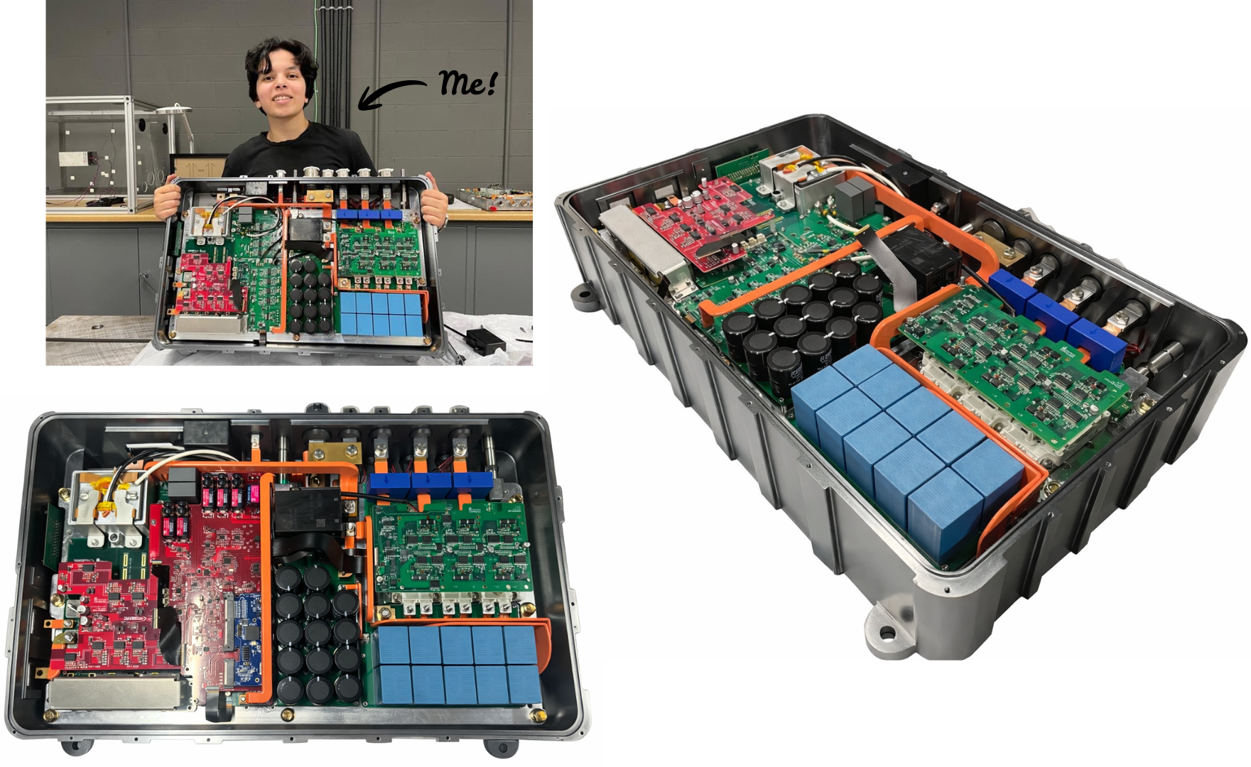
System Integration Layout
The system layout presents the internal arrangement of the 4-in-1 converter components within the housing. Major subsystems such as the power modules, capacitor bank, control board, and transformer are positioned to ensure efficient electrical connectivity, thermal management, and compact packaging.
Design Overview
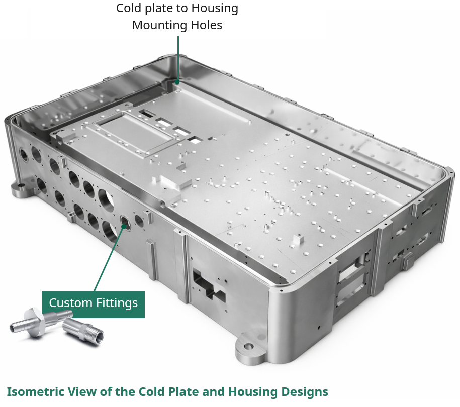
Challange 1: Ensuring assembly feasibility
Solution: The housing and cold plate were designed as two separate components to facilitate manufacturing, assembly, and testing. Custom fittings were implemented to connect the housing inlet and outlet to the corresponding cold plate ports, ensuring proper coolant flow.
Challange 2: Achieving High Power Density
Solution: By mounting electronic components on both sides of the cold plate, the overall system footprint and volume are reduced, enabling a more compact architecture and significantly increasing the power density.
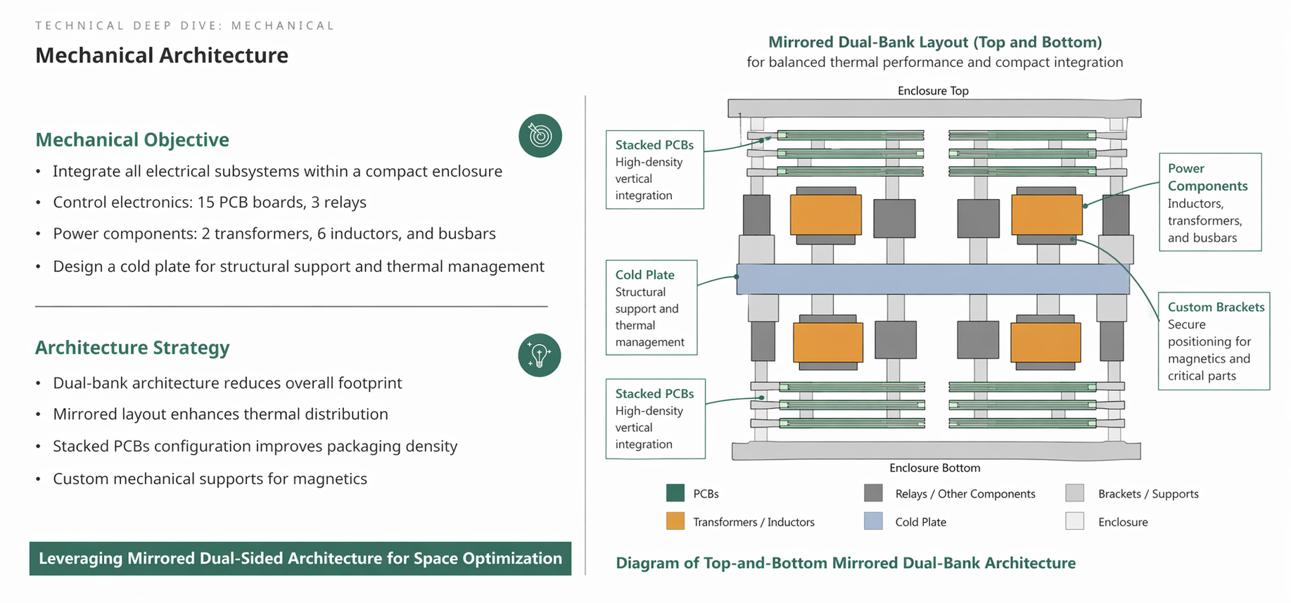
Challange 3: Arranging electrical and mechanical components within limited space
Solution: High-power components were mounted directly on the cold plate to enable efficient thermal management, while low-loss control electronics were stacked above to maximize space utilization. Custom brackets and mounting features were also designed to securely position magnetic components and PCBs, ensuring structural integrity and assembly accessibility while maintaining a compact system footprint.
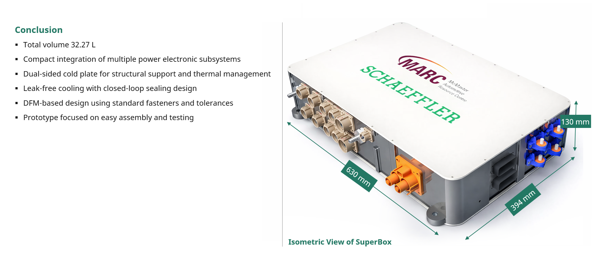
Manufactured design